


Harold Hall


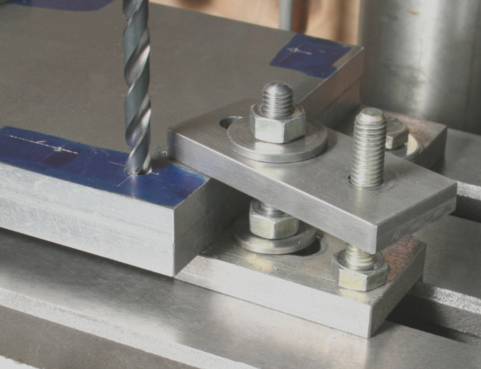
Yet another version, having continuous adjustment for the height of the packing, and again one that I use frequently, is for the clamp bar itself to have a tapped hole and for a screw added to act as a built in jack, Photograph 6. This method is particularly good for low packing heights. Again, machine away the raised lettering on the head of the screw. To prevent the drill hitting the worktable note how in this example a clamp bar has also been placed under the workpiece to raise it from the machine table.
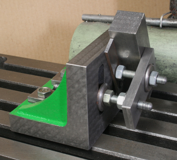
Using a stud to provide the adjustable packing is equally at home for mounting items
onto an angle plate as Photograph 7 shows. In this case though, the packing stud
can be firmly anchored in the slot of the angle plate before the height of the clamp
bar is set. A major advantage of this method if multiple parts are being made is
that the clamp will remain firmly in place between removing the finished part and
fitting another. It will only be necessary to loosen clamping nut as flexibility
in the set-
In this set-
Additional Supports
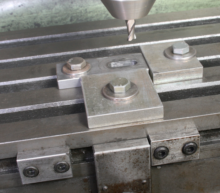
Working with a single clamp should normally be taboo, certainly when the part being held does not provide for easy and secure clamping. In some cases though, access can be limited and getting more than one in place difficult. In this case, providing the part is not over complex and the machining operation not too arduous, additional support around the part will ensure a sufficiently secure mounting is achieved. Photograph 8 shows an example.
The Photograph shows the slot in a small clamp bar being made and illustrates another possibility, that is, sometimes holes in the component itself can be used for securing it. Actually, in this case, the two supports have added benefits in that further parts can be positioned so that the groove can be made without the need for measurement or reference to the leadscrew dials. All that is required is that the table stops, seen lower part of the Photograph, are suitably set, the process then is quick and easy. You see, there is no reason why you should not make a quantity of each size of clamp made.

6
7

8