


Harold Hall
Metalworking
Workshop Set Ups
Milling Machine Table, Setups . Harold Hall



I am of the opinion that many workshop owners are over biased towards using the table vice, as a result, give little thought to mounting the workpiece directly onto the mill table. This page illustrates a few examples of the alternative.
Photo 1 shows a simple task of slotting some workpiece clamps, The two fences, front and right ensure each clamp is positioned identically and the table stops, bottom of the picture, positions and sets the length of the slot. Note that the clamp is secured to the table with a screw through it, rather than an overhead clamp.
Photographs 2 to 5 are some of the operations in making a travelling steady. Photo 2, the recess for the lower arm and Photo 3 being set for making the recess for the upper arm. Photo 4 shows, after the main area of the rest has been removed using a rotary table, being set for finally shaping the rest, Photo 5. LINK
Photos 6 and 7 shows the tee slots being made on the body of my Alternative to a four jaw chuck it also doubles as a very robust tee slotted faceplate. To position the tee slots it revolves around a spindle fixed to the table and is set by the marks on it being aligned with those on the adjacent post.
A a recess being milled along the length of the part in Photo 8 The centre clamp is just a fence to position it the outer ones secure it. Further parts could then be made without any need for measuring.
Sometimes a drill or end mill will need to break through the bottom of the workpiece,. Photos 9 and 10 show how a clamp first secured to the table will raise it and is then secured with an overhead clamp.
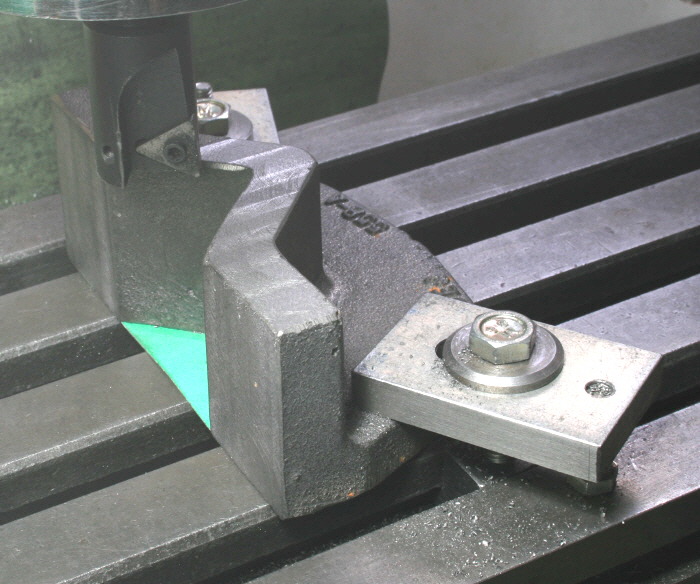
A casting is being machined in Photo 11 whilst clamped to the mill table. However, the lower surface is still in its cast state, high points suitably removed of course, and is placed on a piece of thin hard card to compensate for the irregularities. LINK
The casting in Photo 12 needed to be machined completely over the upper surface preventing overhead clamps being used. Low profile end clamps had to be used therefore. The clamp being used is one my my five designs. LINK
Photographs 13 and 14 are not actually workpieces clamped to the mill table but I have decided to include them here.. Photo 13 shows the surface mentioned in photograph 11 being machined whilst the casting is being supported using two square posts.
Photo 14 shows my method of securing round parts on the mill table which has benefits over using a vee block as shown on the right. Follow the link for an explanation of the method. LINK Photo 15 shows the method can also be used on the faceplate. LINK
All pictures can be clicked on to provide a larger view


1
2


3
4


5
6


7
8


9
10

11
12


13


14
15